Learn all about Capacitors
What is a capacitor ?
A two-terminal electrical component is a capacitor.
They are one of the most essential passive components we employ, along with resistors and conductors.
To locate a circuit that didn't contain a capacitor, you would have to seek extremely hard.
How Does a Capacitor work ?
Consider the parallel plate capacitor, the most fundamental form of a capacitor, as an example. It has two parallel plates that are separated by a dielectric.
One plate is attached to the positive end (plate I) and the other to the negative end when a DC voltage source is applied across the capacitor (plate II).
Plate I turns positive in relation to plate II when the battery's voltage is applied across the capacitor.
The capacitor attempts to conduct steady-state electricity from its positive plate to its negative plate.
But because the plates are separated by an insulating substance, it cannot flow.
When the battery is removed from the capacitor, the two plates hold a negative and positive charge for a certain time.
Thus, the capacitor acts as a source of electrical energy.
If these plates are connected to a load, the current flows to the load from Plate I to Plate II until all the charges are dissipated from both plates.
This time span is known as the discharging time of the capacitor.
Capacitor Symbols
There are two typical methods for representing a capacitor in a schematic.
Always having two terminals, they are connected to the rest of the circuit by these.
Two parallel lines, either flat or curved, should be close but not touching in order for the capacitor symbol to accurately depict how the capacitor is constructed.
Hard to explain, better to just demonstrate:
Fig. 1 and Fig. 2 are standard capacitor circuit symbols. Fig.3 is an example of capacitors symbols in action in a voltage regulator circuit.
The symbol with the curved line Fig. 2 in the photo above) indicates that the capacitor is polarized, meaning it's probably an electrolytic capacitor.
Charging and Discharging of Capacitor
When positive and negative charges coalesce on the capacitor plates, the capacitor becomes charged.
A capacitor can retain its electric field -- hold its charge -- because the positive and negative charges on each of the plates attract each other but never reach each other.
At some point the capacitor plates will be so full of charges that they just can't accept any more.
There are enough negative charges on one plate that they can repel any others that try to join.
This is where the capacitance (farads) of a capacitor comes into play, which tells you the maximum amount of charge the cap can store.
If a path in the circuit is created, which allows the charges to find another path to each other, they'll leave the capacitor, and it will discharge.
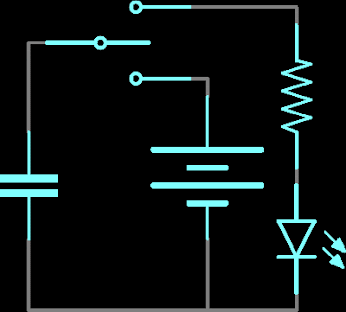
For example, in the circuit below, a battery can be used to induce an electric potential across the capacitor.
This will cause equal but opposite charges to build up on each of the plates, until they're so full they repel any more current from flowing.
An LED placed in series with the cap could provide a path for the current, and the energy stored in the capacitor could be used to briefly illuminate the LED.
Capacitors are common components of
electronic circuits, used almost as frequently as resistors.
The basic
difference between the two is the fact that capacitor resistance (called
reactance) depends on the frequency of the signal passing through the item.
The
symbol for reactance is Xc and it can be calculated using the
following formula:
Block-Capacitors
Block capacitors, also known as capacitors with set values, are made out of two thin metal plates, or "electrodes," that are spaced apart by a thin insulating layer, usually made of plastic.
Aluminum is the substance that "plates" are most frequently made of, whereas mica, ceramic, paper, and other materials are frequently employed as insulators, giving capacitors their names.
In the image below, a variety of block-capacitors are displayed. A capacitor sign may be seen in the image's upper right corner.
Most of the
capacitors, block-capacitors included, are non-polarized components, meaning
that their leads are equivalent in respect of the way the capacitor can be
placed in a circuit.
Electrolytic capacitors represent the exception as their
polarity is important.
Marking
the Block-Capacitors
Capacity-related statistics are frequently used to identify capacitors.
A second number that represents the maximum working voltage is displayed next to first one, and occasionally tolerance, temperature coefficient, and other data are shown as well.
However, there are no markings at all on the tiniest capacitors (such as surface-mount), therefore you must wait to use them before removing them from their protective strips.
The number of layers or "plates" and the dielectric might differ from one manufacturer to the next, therefore the size of a capacitor is never an accurate indicator of its worth.
A capacitor with the value 4n7/40V in a circuit diagram has a capacitance of 4,700 pF and a 40 v maximum working voltage.
Although they are bigger and more expensive, any other 4n7 capacitor with a greater maximum operating voltage can be used.
Sometimes, capacitors are identified
with colors, similar to the 4-band system used for resistors (figure 2.6). The
first two colors (A and B) represent the first two digits, third color (C) is
the multiplier, fourth color (D) is the tolerance, and the fifth color (E) is
the working voltage.
With disk-ceramic capacitors (figure
2.6b) and tubular capacitors (figure 2.6c) working voltage is not specified,
because these are used in circuits with low DC voltage. If a tubular capacitor
has five color bands on it, the first color represents the temperature
coefficient, while the other four specify the capacity in the previously
described way.
|
COLOR
|
DIGIT
|
MULTIPLIER
|
TOLERANCE
|
VOLTAGE
|
|
Black
|
0
|
x 1 pF
|
±20%
|
|
|
Brown
|
1
|
x 10 pF
|
±1%
|
|
|
Red
|
2
|
x 100 pF
|
±2%
|
250V
|
|
Orange
|
3
|
x 1 nF
|
±2.5%
|
|
|
Yellow
|
4
|
x 10 nF
|
|
400V
|
|
Green
|
5
|
x 100 nF
|
±5%
|
|
|
Blue
|
6
|
x 1 µF
|
|
|
|
Violet
|
7
|
x 10 µF
|
|
|
|
Grey
|
8
|
x 100 µF
|
|
|
|
White
|
9
|
x 1000
µF
|
±10%
|
|
The figure 2.2.2b shows how the
capacities of miniature tantalum electrolytic capacitors are marked by colors.
The first two colors represent the first two digits and have the same values as
with resistors.
The third color represents the multiplier, to get the capacity
expressed in µF. The fourth color represents the maximal working voltage.
|
COLOR
|
DIGIT
|
MULTIPLIER
|
VOLTAGE
|
|
Black
|
0
|
x 1 µF
|
10V
|
|
Brown
|
1
|
x 10 µF
|
|
|
Red
|
2
|
x 100 µF
|
|
|
Orange
|
3
|
|
|
|
Yellow
|
4
|
|
6.3V
|
|
Green
|
5
|
|
16V
|
|
Blue
|
6
|
|
20V
|
|
Violet
|
7
|
|
|
|
Grey
|
8
|
x .01 µF
|
25V
|
|
White
|
9
|
x .1 µF
|
3V
|
|
Pink
|
|
|
35V
|
Marking the tantalum electrolytic capacitors
One thing to keep in mind about working voltage:
A capacitor should not have its voltage across it surpass its maximum working voltage because that could cause the capacitor to fail.
The "worst" case should be taken into account when the voltage is unknown.
There is a chance that the voltage on the capacitor will match the power supply voltage if another component malfunctions.
The maximum working voltage for the capacitor should be more than 12V, for instance, if the supply is 12V.
Electrolytic
capacitors
The unique category of capacitors with a fixed capacity value is the electrolytic capacitor.
They can have an incredibly high capacity, ranging from one to several thousand F, thanks to specific construction.
They provide a variety of functions, but filtering is where they are most frequently utilized in circuits.
When attaching an electrolytic capacitor to a circuit, the fact that it is polarized—that is, that it has both positive and negative leads—is crucial.
The location having a higher positive voltage than the negative lead must be linked to via the positive lead or pin.
The insulating layer within the capacitor will "dissolve" if it is connected in reverse, permanently damaging the capacitor.
If a capacitor is linked to a voltage that is higher than its operating voltage, explosion may also result.
One of the capacitor's connectors is very visibly marked with a + or - to help prevent such occurrences, and the working voltage is displayed on the case.
The image below shows a number of electrolytic capacitor models together with their respective symbols.
Electrolytic capacitors
Tantalum capacitors represent a
special type of electrolytic capacitor.
Their parasitic inductance is much
lower than standard aluminum electrolytic capacitors so that tantalum
capacitors with significantly (even ten times) lower capacity can completely
substitute an aluminum electrolytic capacitor.
Variable Capacitors
Capacitors with varying capacities are known as variable capacitors.
Their smallest capacity starts at 1p, while their largest capacity is a few hundred pF.
(500pF max). Variable capacitors are produced in a variety of sizes and shapes, but they all share a set of stationary plates (known as the stator) and a set of moving plates.
These plates fit inside of one another and can be inserted or removed from the mesh by rotating a shaft.
The variable capacitor's name comes from the insulator (dielectric) between the plates, which is either air or a thin layer of plastic.
It's crucial to avoid touching the plates when adjusting these capacitors. Here are images of variable capacitors using mylar insulation and air dielectrics.
a, b, c. Variable capacitors, d. Trimmer capacitors
The first photo shows a "ganged
capacitor" in which two capacitors are rotated at the same time. This type
of capacitor is used in radio receivers.
The larger is used for the tuning
circuit, and the
smaller one in the local oscillator. The symbol for these capacitors is also
shown in the photo.
Beside capacitors with air dielectric,
there are also variable capacitors with solid insulator.
With these, thin
insulating material such as mylar occupies the space between stator and rotor.
These capacitors are much more resistant to mechanical damage. They are shown
in figure 2.2.4b.
The most common devices containing variable
capacitors are radio receivers, where these are used for frequency adjustment.
Semi-variable or trim capacitors are miniature capacitors, with capacity
ranging from several pF to several tens of pFs.
These are used for fine tuning
radio receivers, radio transmitters, oscillators, etc. Three trimmers, along
with their symbol, are shown on the figure d.
===================================================================


No comments:
Post a Comment